Dr. Sajid Muhaimin Choudhury

>

image
Hello,

I'm Dr. Sajid Muhaimin Choudhruy

I am currently working in the Department of Electrical and Electronic Engineering of Bangladesh University of Engineering and Technology, Dhaka-1205. My official website is located at sajid.buet.ac.bd. I previously maintained various personal blogs and websites (sajidmc.net). I decided to move to a permanent web solution to host all my previous blogposts.

Blog

ইউ এস বি এ এস পি এর জন্য নতুন মাস্ক

এই মাস্ক গুলো থমাস ফিচ্যাল এর বানানো ইউ এস বি প্রোগ্রামার এর জন্য আমি বানিয়েছি। (http://www.fischl.de/usbasp/)


I used series resistors with MOSI MISO SCK and RST lines. They are used for protection of the ATmega8 of the programmer. They can be replaced with short circuits like the original design.In my design, the resistors probably causes some rise time issue, so the programmer will not work unless the slow sck jumper is shorted out. And power is not drawn from the USB port, and taken from the external circuit. Reversing polarity of Vcc and GND will certainly cause the programmer to die. I included a Zener Diode in my design to limit the reverse polarity voltage, but don't know how effective it would be. I'll try to make another design with 5 wire-output, that draws power from USB port.


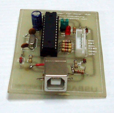
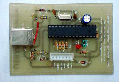
These masks are designed by me for the USB ASP Programmer designed by Tomas Fischl (http://www.fischl.de/usbasp/)


I used series resistors with MOSI MISO SCK and RST lines. They are used for protection of the ATmega8 of the programmer. They can be replaced with short circuits like the original design.In my design, the resistors probably causes some rise time issue, so the programmer will not work unless the slow sck jumper is shorted out. And power is not drawn from the USB port, and taken from the external circuit. Reversing polarity of Vcc and GND will certainly cause the programmer to die. I included a Zener Diode in my design to limit the reverse polarity voltage, but don't know how effective it would be. I'll try to make another design with 5 wire-output, that draws power from USB port.


Creating a PCB: The Toru Bhai Style

Today, I went to make the PCB of my AVR USB Programmer (USBASP). BUET Students usually go to 'Toru Bhai'  for making PCBs. I did my design in Proteus Isis and Ares. I talked to Toru Bhai, and he asked me to bring print out of the masks I designed. Basically 3 masks are required for single layer PCB:

Bottom Copper

Top Components (Silk Screen)

Solder Resist


Although, Toru Bhai is reluctant to do the Solder Resist, as he claims it is too expensive. As I went today in his 'factory', in 6/1/F, Ram Krishna Mission Road, he didn't have much work load and insisted me to wait and take my PCB with me. So I watched the fabrication process. Surprisingly, the screen printing is very much similar to VLSI fabrication. 

Basically, a thin fabric with tiny holes in it is first covered in paint, and the tracing paper with the print out of the pattern is held in front of it. The screen is enclosed in glass, and exposed to solar light. The region covered by ink in the tracing paper remain unchanged, but the region exposed to light hardened. The screen is then washed, and the region covered by ink on tracing paper during solar exposure has its paint removed. 

Then the screen is used to imprint the pattern of the tracing paper on copper board. The paint has to be insoluble to water. After the print, the board is submerged to FeCl3 (Ferric Chloride). Regions not covered by paint has its copper removed, as Copper reacts with FeCl3 to produce Cu-Chloride.

Afterwards, the paint is removed. Then holes are drilled to it, and the top layer patterns are drawn accordingly.

I got some pictures of the process:
The lab:

A screen looks like this:

Fitting the screen

Screen ready for action
Patternizing
FeCl3 Etching

Drilling Holes

Grinder used to smoothen the sides


USBASP Programmer for AVR is working on Windows Vista


Finally I could get my USB programmer to work with windows vista. Firstly, I stripped of the breadboard from all previous connections, and reconnected the circuit. This ofcourse proved fatal to two of my microcontrollers, as I accidentally connected +12V to Vcc rail, instead of the input to the 7805 IC. I connected the programmer to PC, and it said unknown device. I knew I connected the D+ and D- wires from USB port wrong. The final bread board looks like this:


So I swapped them and replugged the USB. This time the device was recognised as usbasp, and windows vista asked for driver. I supplied the libusb driver given with the fischel's package (http://www.fischl.de/usbasp/). Windows said something about device compatibiliy. I chose to ignore, and the device installed successfully.

Now I opened command prompt and typed  avrdude -c usbasp -p t2313

 Command prompt returned  error: could not find USB device "USBasp" with vid=0x16c0 pid=0x5dc


I tried to search the forums. They suggested to use 2007 build of winavr, I tried that (replaced avrdude.exe in the C:\winavr\bin directory with the 2007 version). Some of them also suggested to use an older version of libusb. So I did that too. After spending an hour, I did some thing I should have done a long time ago. I clicked on the orb (start), typed 'cmd', so Vista start menu searched cmd.exe. I right clicked on it and selected "Run as Administrator". Now when I typed

C:\Windows\system32>avrdude -c usbasp -p t2313
found 8 busses

avrdude: AVR device initialized and ready to accept instructions

Reading | ################################################## | 100% 0.02s

avrdude: Device signature = 0x1e910a

avrdude: safemode: Fuses OK

avrdude done.  Thank you.

Wow, the device actually worked!! I tried several times and it was working. I started the AVR8-Burn-O-Mat and changed some settings.


Burn O Mat seems to work fine too. Just too bad it doesn't have the buffer of ponyprog, and the hex display. It is just great otherwist, and has a lot better fusebit editor.


Visit My Official Website at BUET

Contact Me
Sajid Choudhury
+9665650
Dhaka, Bangladesh