(Really) Beginners Microcontroller Guide (Part-II) Configuring Ponyprogproperly and writing program to uC
(A Continuation from (Really) Beginners Microcontroller Guide (Part-I) Compiling the first program)
(alpha version. Very unstable, still editing)
Writing program to Microcontroller
We will be using ponyprog from lancos. Although it is possible to program directly from winavr, I like the interface of the program very much.
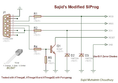
Construct the simplified SI Prog. You'll need:
1. A serial port DB9 Female Connector,
2. 5V1 Zener Diodes x3
3. Resistors: 15K, 10k, 4k7 x 3
4. Bread board wires
Connect the circuit on veroboard. To see how it looks go to my blog http://sajiduc.blogspot.com/2008/04/beginners-microcontroller-programming.html
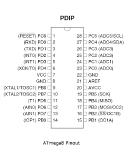
To connect the programmer always consult the datasheet of the microcontroller. Connect the Mosi, MISO, SCK, Reset lines of the programmer to the corresponding pins of microcontroller, and connect GND to 0V. Connect the serial connector to the serial port of your mother board. Please do not use a usb-serial converter, and connect only to true serial port.
Goto http://www.lancos.com/prog.html and download ponyprog from there. Install ponyprog, and open ponyprog from startmenu.
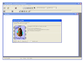
After the annoying neigh sound, click ok. Pony prog will say
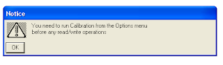
Click ok again
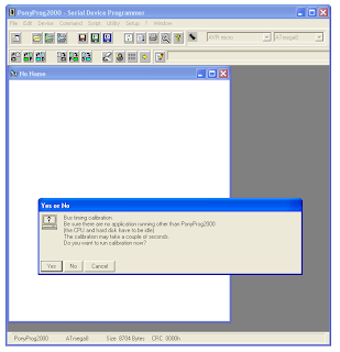
Now do the bus timing calibration:
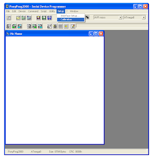
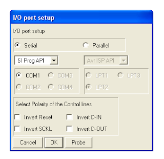
Afterwards, it is important. Click Setup>Interface Setup. Select Serial radio button. From drop down select SI Prog API / SI Prog IO. Select the COM port in which the programmer is connected. It is COM1 if you have only one serial port, but for multiple ports, you have to select the appropriate one. Please note that 90% cases, the SIProg does not work because of not proper configuration in this dialog. So if the SI Prog does not work, try to change the COM port, or switch between SI Prog API and IO
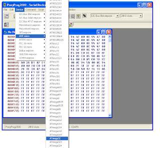
Select the appropriate device name
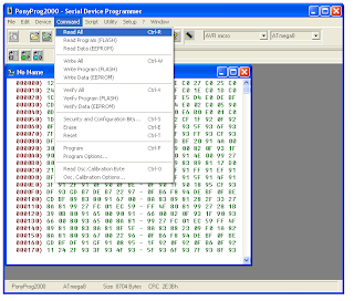
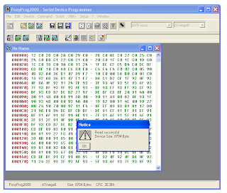
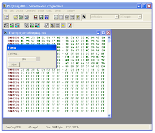
Now to test if the programmer is working, Click Command>Read All. From my experience 70% cases, people don't get a smooth read operation at the first try. See below for common problems
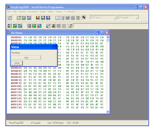
If every thing is ok, (Which actually did in my first experimental SIProg) Then reading will start.
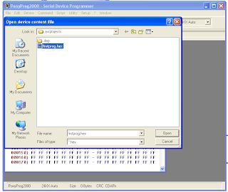
Now click File>Open, and open the testprog.hex file generated by the compiler.
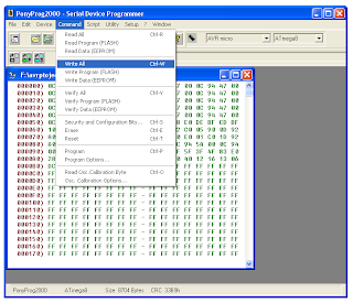
Now select write all
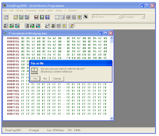
And then the write will be successful!
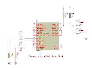
Then play with your microcontroller circuit:
Ofcource the write may not be successful.
This might be due to
1. Circuit connection error (Check if you have connected power to micr
ocontroller, check if the breadboard connections are loose, if the programmer are connected to the proper pins, if the programmer is soldered properly.)
2. Check if the BC547 transistor is working by testing if 0.7 V drop occus between Emitter and Base.
3. Check if your serial port is working and you are not using a USB-serial converter
4. Play around with the interface setup (in ponyprog) to find another suitable setting for you. (Try SIprog API, SIProg IO, Check if you have selected correct serial port)
5. This is very common for me:- the microcontroller is dead!!!!
Well, no 5 can result from 2 cases, a) a heart attack of the microcontroller (Fry out, like connecting Vcc of microcontroller to ground and ground to Vcc, microcontroller, at 90% cases just fry) b) Accidental programming of the fusebits of the microcontroller can result the SPI interface to be locked out. This can be overcome by a universal programmer. If you happen to have access to one, ask some one clear the lock bits.
6. You forgot to select the right device (I also sometimes forget to do that)
(alpha version. Very unstable, still editing)
Writing program to Microcontroller
We will be using ponyprog from lancos. Although it is possible to program directly from winavr, I like the interface of the program very much.
Construct the simplified SI Prog. You'll need:
1. A serial port DB9 Female Connector,
2. 5V1 Zener Diodes x3
3. Resistors: 15K, 10k, 4k7 x 3
4. Bread board wires

Connect the circuit on veroboard. To see how it looks go to my blog http://sajiduc.blogspot.com/2008/04/beginners-microcontroller-programming.html


To connect the programmer always consult the datasheet of the microcontroller. Connect the Mosi, MISO, SCK, Reset lines of the programmer to the corresponding pins of microcontroller, and connect GND to 0V. Connect the serial connector to the serial port of your mother board. Please do not use a usb-serial converter, and connect only to true serial port.
Goto http://www.lancos.com/prog.html and download ponyprog from there. Install ponyprog, and open ponyprog from startmenu.

After the annoying neigh sound, click ok. Pony prog will say

Click ok again
Now do the bus timing calibration:


Afterwards, it is important. Click Setup>Interface Setup. Select Serial radio button. From drop down select SI Prog API / SI Prog IO. Select the COM port in which the programmer is connected. It is COM1 if you have only one serial port, but for multiple ports, you have to select the appropriate one. Please note that 90% cases, the SIProg does not work because of not proper configuration in this dialog. So if the SI Prog does not work, try to change the COM port, or switch between SI Prog API and IO

Select the appropriate device name

Now to test if the programmer is working, Click Command>Read All. From my experience 70% cases, people don't get a smooth read operation at the first try. See below for common problems

If every thing is ok, (Which actually did in my first experimental SIProg) Then reading will start.


Now click File>Open, and open the testprog.hex file generated by the compiler.

Now select write all


And then the write will be successful!
Then play with your microcontroller circuit:
Ofcource the write may not be successful.
This might be due to
1. Circuit connection error (Check if you have connected power to micr
ocontroller, check if the breadboard connections are loose, if the programmer are connected to the proper pins, if the programmer is soldered properly.)
2. Check if the BC547 transistor is working by testing if 0.7 V drop occus between Emitter and Base.
3. Check if your serial port is working and you are not using a USB-serial converter
4. Play around with the interface setup (in ponyprog) to find another suitable setting for you. (Try SIprog API, SIProg IO, Check if you have selected correct serial port)
5. This is very common for me:- the microcontroller is dead!!!!
Well, no 5 can result from 2 cases, a) a heart attack of the microcontroller (Fry out, like connecting Vcc of microcontroller to ground and ground to Vcc, microcontroller, at 90% cases just fry) b) Accidental programming of the fusebits of the microcontroller can result the SPI interface to be locked out. This can be overcome by a universal programmer. If you happen to have access to one, ask some one clear the lock bits.
6. You forgot to select the right device (I also sometimes forget to do that)


 Beginners Microcontroller Guide (Part-I) Compiling the first program ) (alpha version. Very unstable, stil...)
I have tried the programmer, but get "Unknown device". All the signals come to the AVR, measured with oscolliscope, except for MISO wich is constant 0V.
ReplyDeleteAny idea what I could try?
Mikael: have you tried a different microcontroller? MISO is the pin where programmer listens, microcontroller speaks. If that is silent, it means microcontroller isn't speaking.
ReplyDeleteSorry, I accidentialy wrote two comments about the same problem.
ReplyDeleteThank you for a very quick answer.
I will try another atmega48, which is what I use. But it have never been programmed before so I think it is strange... But also strange things happens in electronics ;)
Just wanted to tell you that it worked with a new microcontroller. This time I also disconnected a MAX202 and ULN2803 from their sockets, previously connected to the atmega48. Maybe they damaged the unprogrammed µC.
ReplyDeleteThanks for letting me know. Are you connecting the ULN2803's input to the MOSI, MISO or SCK pins? I read a book that recommended using pull up resistors of 10k / 4.7k in ULN input when connecting to microcontroller, as microcontroller cannot source high current.
ReplyDeleteYes, all of the programming pins are also connected to the ULN. I don't use pullup-resistors as it works great without them and this projects PCB is crowded already.
ReplyDeleteNow the only problem is that the atmega won't respond to commands from the MAX202 instead.
Before I integrated this programmer I programmed with my stk500 from AVRstudio, maybe then it set some fuse bits which is not included in the hex file..
I used a USB to serial converter and it wasn't working at first. I found out my converter's TxD wasn't working when I was using avrdude. So I got rid of the transistor altogether and forced the reset pin to ground during programming. Now it works great, thanks a lot for the post.
ReplyDeletewow, thanks Tonmoy for the information. But TXD is a critical serial communication pin. It should not be skipped from the dongle. did you check how much voltage is available at the output of TXD? I always thought that the other pins are not implemented, but TXD is basic...
ReplyDeletethe TxD was always constant to 15V so it was preventing my mC to going to reset mode. That's why I kept the TxD open circuited. I figured that the converter probably had built in safety. I was using the power supply from another usb and so I could get rid of the pin 5 of the serial port as well. This is the only solution that seems to work for me. I guess I should make a USBasp instead of taking such risks.
ReplyDeleteGreat job, I think this would be Really a nice and Simplified tutorial for beginners. Good job Sajid .. 5 starts from me.
ReplyDeleteRegards
Ron
http://www.rakeshmondal.info/